AI Networking pinned
EVPN Multihoming Across Vendors, Part 1: From Configuration to Control Plane Alignment
Four leaves, two vendors, one Ethernet Segment. Five configuration differences between Cumulus and Arista stand between the RFC and a working all-active bond — four get solved here, and none of them are in the RFC.
on this page
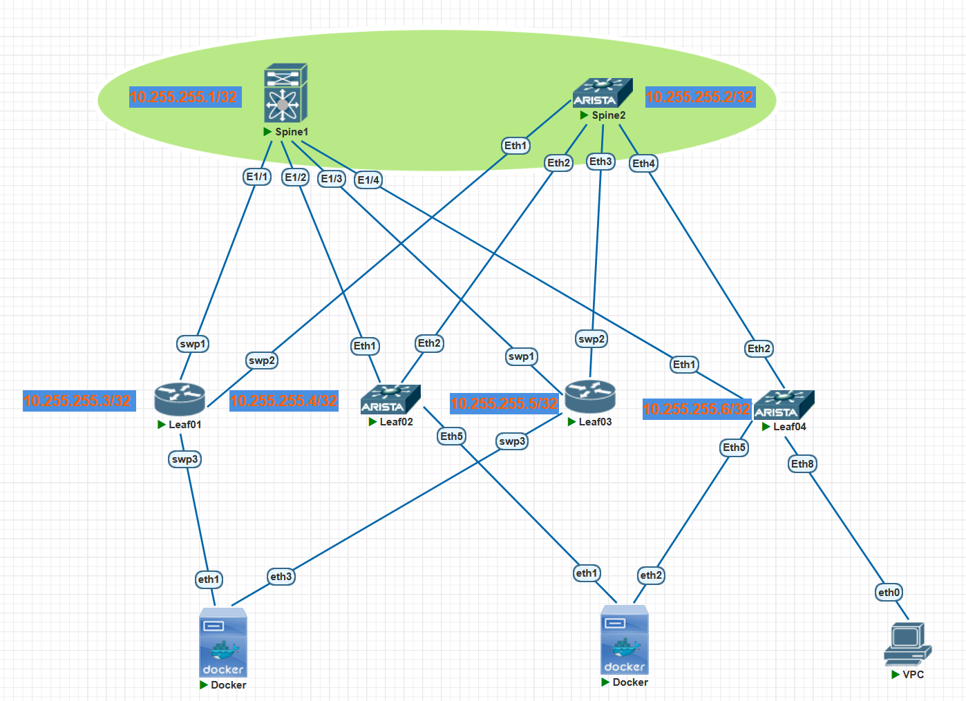
Following on from the last article, with BGP unnumbered now sorted out, it is time to look at native EVPN multihoming. The topology:
About the lab environment
Everything described here comes from a PNetLab virtual environment involving Cumulus VX 5.9.1, Arista vEOS-lab 4.32.4M and Nexus 9000v 10.5(2). The interoperability, forwarding behaviour and offload symptoms described are specific to that combination and are not directly equivalent to the behaviour of real switching silicon or other software versions.
ESI (Ethernet Segment Identifier)#
In the traditional approach, getting a server dual-homed to two switches with both links forwarding means MLAG or vPC. That family of solutions has three limits you cannot get around: it is vendor-proprietary (Cisco’s vPC and Arista’s MLAG do not recognise each other), it essentially supports only two switches, and it needs an additional peer-link and keepalive path to synchronise state. EVPN’s ESI multihoming, by contrast, is an RFC-defined standard mechanism that in principle works across vendors and needs no dedicated peer link.
ES (Ethernet Segment)#
RFC 7432 §5 gives the definition: when a server connects over a set of links to one or more leaves, those links constitute an ES, identified by a globally unique ESI.
The definition looks unremarkable, and every mechanism in multihoming is built on it. All the leaves that claim the same ESI automatically constitute the member set for that segment in the EVPN control plane. Nobody has to configure a membership table, and the members do not need to establish a dedicated channel between themselves. Each PE simply advertises “this interface of mine belongs to ESI X” over BGP, and any device receiving the same ESI advertisement naturally knows they are in the same segment.
EVPN does not replicate the peer-link with another dedicated link. Instead it distributes member discovery, MAC/IP reachability, failure withdrawal, split horizon and so on into the distributed control plane and into each PE’s local forwarding mechanisms.
ESI format#
An ESI is a fixed 10 bytes: the high-order byte indicates the type and the remaining 9 bytes are the value. Two reserved values: all zeros means single-homed, all Fs (MAX-ESI) is reserved.
| Type | Derived from | ESI value composition |
|---|---|---|
| 0 | Manual configuration | Any 9 bytes; the administrator guarantees network-wide uniqueness |
| 1 | Automatically from the CE’s LACP parameters | System MAC (6 bytes) + Port Key (2 bytes) + 00 |
| 2 | Automatically from the CE-side STP root bridge | Root Bridge MAC (6 bytes) + Priority (2 bytes) + 00 |
| 3 | From the PE’s system MAC | System MAC (6 bytes) + Local Discriminator (3 bytes) |
| 4 | From the Router ID | Router ID (4 bytes) + Local Discriminator (4 bytes) + 00 |
| 5 | From the AS number | AS Number (4 bytes) + Local Discriminator (4 bytes) + 00 |
In real deployments Type 0 and Type 3 are the most used. Type 1 is worth noting separately: it is the only type that derives the ESI backwards from the CE’s LACP parameters, which makes the segment identity on the switch side follow the aggregation identity on the access side naturally.
Two multihoming modes#
RFC 7432 defines two:
- Single-Active — at any given moment only one PE forwards traffic for a given VLAN on that segment, the rest stand by. Suited to situations where traffic reordering is unacceptable, or where the CE does not support link aggregation.
- All-Active — every PE in the segment forwards simultaneously, and the CE uses LACP to bundle multiple uplinks into one logical port. This is the form that replaces MLAG/vPC, and it is the mode this article is concerned with.
The “only two switches” limit is broken here: the protocol itself does not restrict an ES to two PEs. How many can actually be attached is still constrained by vendor, hardware platform and software version, and the access side must also have a corresponding number of physical links to bundle.
Four supporting mechanisms#
Multihoming looks like several devices sharing one identifier, but to actually make it run, EVPN multihoming is built around the four key mechanisms below. The base mechanisms come mainly from RFC 7432, with the VXLAN-specific handling of split horizon and so on further specified by RFC 8365. Each one solves a specific problem:
| Mechanism | What it solves | Route type it depends on |
|---|---|---|
| DF election | If every PE delivered BUM traffic to the CE, the CE would receive duplicates. Only one PE per segment per VLAN is elected to forward BUM | Type-4 |
| Split horizon | BUM sent by the CE, once flooded, can come back round to another PE in the same segment and be delivered to the CE again, forming a loop | ESI Label (Local Bias under VXLAN) |
| Aliasing | A given MAC may be learned by only one PE; if remote devices honour only that one route, all traffic piles onto that PE | Type-1 EAD per-EVI |
| Fast withdrawal | When an ES link fails, there may be tens of thousands of MACs behind it that need withdrawing; doing that one at a time converges far too slowly | Type-1 EAD per-ES |
Of these, DF election and aliasing provide multiple usable next hops; they do not guarantee that evenly balanced load will be observable at every instant. Without aliasing, even with four PEs in the segment, traffic only uses whichever one learned the MAC, and all-active becomes all-active in name only.
Split horizon has an important difference under VXLAN: in the MPLS case the ESI Label marks the origin of a frame, but the VXLAN data plane encapsulation does not carry an MPLS ESI Label. RFC 8365 therefore defines Local Bias: the receiver judges from the outer source IP which PE a frame came from, and if that PE is in the same segment as itself, it does not forward the frame to local ES ports. Different mechanism, same purpose.
Back to the three limits#
| Limit of MLAG / vPC | How ESI addresses it |
|---|---|
| Vendor-proprietary, cannot cross vendors | ESI, Type-1/Type-4 routes and DF election are all defined by RFC; every vendor implements the same protocol |
| Essentially supports only two switches | The number of segment members is not limited by the protocol; several PEs simply claim the same ESI |
| Requires a peer-link and keepalive path | ES member discovery and the associated reachability advertisement happen over BGP EVPN; no separate peer-link is needed between these PEs |
It is worth saying that “works across vendors in theory” and “configures smoothly” are two different things. The RFC covers ESI semantics and route formats; it does not cover how each vendor derives the ESI, which configuration granularity they expose, or what their default values are. Those differences only surface when you actually connect to another vendor. Enough theory — time to build it.
Base configuration (BGP + EVPN)#
I will not walk through this in detail; the official documentation covers it if you are interested.
Spine1#
Nexus 9000v, version 10.5(2). Official documentation
nv overlay evpn
feature bgp
feature nv overlay

route-map RMAP-NHU permit 10
  set ip next-hop unchanged

interface Ethernet1/1
  no switchport
  ip forward
  ipv6 address use-link-local-only
  ipv6 nd ra-interval 4 min 5
  ipv6 nd ra-lifetime 10
  no shutdown

interface Ethernet1/2
  no switchport
  ip forward
  ipv6 address use-link-local-only
  ipv6 nd ra-interval 4 min 5
  ipv6 nd ra-lifetime 10
  no shutdown

interface Ethernet1/3
  no switchport
  ip forward
  ipv6 address use-link-local-only
  ipv6 nd ra-interval 4 min 5
  ipv6 nd ra-lifetime 10
  no shutdown

interface Ethernet1/4
  no switchport
  ip forward
  ipv6 address use-link-local-only
  ipv6 nd ra-interval 4 min 5
  ipv6 nd ra-lifetime 10
  no shutdown

interface loopback0
  ip address 10.255.255.1/32

router bgp 65001
  router-id 10.255.255.1
  bestpath as-path multipath-relax
  address-family ipv4 unicast
    network 10.255.255.1/32
    maximum-paths 2
  address-family l2vpn evpn
    retain route-target all
  neighbor Ethernet1/1
    remote-as 65002
    address-family ipv4 unicast
    address-family ipv6 unicast
    address-family l2vpn evpn
      send-community extended
      route-map RMAP-NHU out
  neighbor Ethernet1/2
    remote-as 65003
    address-family ipv4 unicast
    address-family ipv6 unicast
    address-family l2vpn evpn
      send-community extended
      route-map RMAP-NHU out
  neighbor Ethernet1/3
    remote-as 65004
    address-family ipv4 unicast
    address-family ipv6 unicast
    address-family l2vpn evpn
      send-community extended
      route-map RMAP-NHU out
  neighbor Ethernet1/4
    remote-as 65005
    address-family ipv4 unicast
    address-family ipv6 unicast
    address-family l2vpn evpn
      send-community extended
      route-map RMAP-NHU out
Spine2#
Arista vEOS-lab, version 4.32.4M. Official documentation
Sharp-eyed readers may notice that I have assigned MAC addresses to Ethernet2 through Ethernet4. That is because Arista cannot use the same IPv6 link-local address on multiple interfaces — if it does, the BGP neighbours will not come up. The manually configured MACs increment the last digit of the device’s own MAC address.
interface Ethernet1
   no switchport
   ipv6 enable
   ipv6 nd ra interval msec 4000 3000
   ipv6 nd ra lifetime 10
!
interface Ethernet2
   mac-address 50:b5:b6:dd:9a:76
   no switchport
   ipv6 enable
   ipv6 nd ra interval msec 4000 3000
   ipv6 nd ra lifetime 10
!
interface Ethernet3
   mac-address 50:b5:b6:dd:9a:77
   no switchport
   ipv6 enable
   ipv6 nd ra interval msec 4000 3000
   ipv6 nd ra lifetime 10
!
interface Ethernet4
   mac-address 50:b5:b6:dd:9a:78
   no switchport
   ipv6 enable
   ipv6 nd ra interval msec 4000 3000
   ipv6 nd ra lifetime 10
!
interface Loopback0
   ip address 10.255.255.2/32
!
ip routing ipv6 interfaces
!
ipv6 unicast-routing
!
router bgp 65001
   router-id 10.255.255.2
   neighbor LEAF peer group
   neighbor LEAF next-hop-unchanged
   neighbor LEAF send-community extended
   neighbor interface Et1 peer-group LEAF remote-as 65002
   neighbor interface Et2 peer-group LEAF remote-as 65003
   neighbor interface Et3 peer-group LEAF remote-as 65004
   neighbor interface Et4 peer-group LEAF remote-as 65005
   !
   address-family evpn
      neighbor LEAF activate
   !
   address-family ipv4
      neighbor LEAF activate
      neighbor LEAF next-hop address-family ipv6 originate
      network 10.255.255.2/32
   !
   address-family ipv6
      neighbor LEAF activate
Leaf01 and Leaf03#
Cisco is not used for the leaf nodes here — Cisco’s ESI support requires hardware support — so the choice is Cumulus, which is friendlier to software, version 5.9.1. Official documentation
The BGP router ID and the source address for EVPN updates both use the loopback0 address; the local VLAN is 10 and the VNI is 10010:
nv set system hostname Leaf01

nv set interface lo ip address 10.255.255.3/32
nv set interface swp1,swp2

nv set router bgp enable on
nv set router bgp autonomous-system 65002
nv set router bgp router-id 10.255.255.3

nv set vrf default router bgp neighbor swp1 remote-as external
nv set vrf default router bgp neighbor swp2 remote-as external
nv set vrf default router bgp address-family ipv4-unicast enable on
nv set vrf default router bgp address-family ipv4-unicast redistribute connected enable on

nv set evpn enable on
nv set vrf default router bgp address-family l2vpn-evpn enable on
nv set vrf default router bgp neighbor swp1 address-family l2vpn-evpn enable on
nv set vrf default router bgp neighbor swp2 address-family l2vpn-evpn enable on

nv set nve vxlan enable on
nv set nve vxlan source address 10.255.255.3
nv set nve vxlan arp-nd-suppress on

nv set bridge domain br_default vlan 10
nv set bridge domain br_default vlan 10 vni 10010
nv set evpn vni 10010 route-target both 10:10

nv config apply
nv config save
Leaf03’s configuration is the same, so I will not paste it — just change interface lo, router-id and vxlan source address.
Leaf02 and Leaf04#
Arista vEOS-lab, version 4.32.4M. Official documentation
Leaf04’s configuration is the same too, so again not pasted — just change interface lo and router-id.
vlan 10
!
interface Ethernet1
   no switchport
   ipv6 enable
   ipv6 nd ra interval msec 4000 3000
   ipv6 nd ra lifetime 10
!
interface Ethernet2
   no switchport
   ipv6 enable
   ipv6 nd ra interval msec 4000 3000
   ipv6 nd ra lifetime 10
!
interface Loopback0
   ip address 10.255.255.4/32
!
ip routing ipv6 interfaces
!
ipv6 unicast-routing
!
interface Vxlan1
   vxlan source-interface Loopback0
   vxlan udp-port 4789
   vxlan vlan 10 vni 10010
!
router bgp 65003
   router-id 10.255.255.4
   maximum-paths 2 ecmp 2
   neighbor SPINE peer group
   neighbor SPINE send-community extended
   neighbor interface Et1-2 peer-group SPINE remote-as 65001
   !
   vlan 10
      rd 10.255.255.4:10
      route-target both 10:10
      redistribute learned
   !
   address-family evpn
      neighbor SPINE activate
   !
   address-family ipv4
      neighbor SPINE activate
      neighbor SPINE next-hop address-family ipv6 originate
      network 10.255.255.4/32
   !
   address-family ipv6
      neighbor SPINE activate
Verifying BGP state#
Neighbour state on Spine1 is fine. Next, Spine2.
Spine1# show bgp sessions
Total peers 4, established peers 4
ASN 65001
VRF default, local ASN 65001
peers 4, established peers 4, local router-id 10.255.255.1
State: I-Idle, A-Active, O-Open, E-Established, C-Closing, S-Shutdown

Neighbor        ASN    Flaps LastUpDn|LastRead|LastWrit St Port(L/R)  Notif(S/R)
fe80::520d:a5ff:fef6:af4%Ethernet1/2
                65003 1     04:17:40|00:00:16|00:00:04 E   179/43353      1/0
fe80::52ad:1ff:fe67:dd4a%Ethernet1/4
                65005 1     04:17:30|00:00:26|00:00:05 E   179/33563      1/0
fe80::52c8:47ff:fe00:1001%Ethernet1/1
                65002 10    00:16:01|00:00:02|00:00:02 E   179/52054      2/8
fe80::52cc:f2ff:fe00:1301%Ethernet1/3
                65004 4     00:40:39|00:00:01|00:00:02 E   179/44166      0/4

Spine1# show bgp l2vpn evpn summary
BGP summary information for VRF default, address family L2VPN EVPN
BGP router identifier 10.255.255.1, local AS number 65001
BGP table version is 156, L2VPN EVPN config peers 4, capable peers 4
5 network entries and 5 paths using 1500 bytes of memory
BGP attribute entries [4/1472], BGP AS path entries [3/18]
BGP community entries [0/0], BGP clusterlist entries [0/0]

Neighbor        V    AS    MsgRcvd    MsgSent   TblVer  InQ OutQ Up/Down  State/
PfxRcd
fe80::520d:a5ff:fef6:af4%Ethernet1/2
                4 65003        448        353      156    0    0 04:18:33 1

fe80::52ad:1ff:fe67:dd4a%Ethernet1/4
                4 65005        443        355      156    0    0 04:18:23 0

fe80::52c8:47ff:fe00:1001%Ethernet1/1
                4 65002       6199       5930      156    0    0 00:16:54 3

fe80::52cc:f2ff:fe00:1301%Ethernet1/3
                4 65004       1900       1815      156    0    0 00:41:32 1


Neighbor        T    AS Type-1     Type-2     Type-3     Type-4     Type-5     T
ype-12
fe80::520d:a5ff:fef6:af4
                I 65003 0          0          1          0          0          0

fe80::52ad:1ff:fe67:dd4a
                I 65005 0          0          0          0          0          0

fe80::52c8:47ff:fe00:1001
                I 65002 1          1          1          0          0          0

fe80::52cc:f2ff:fe00:1301
                I 65004 0          0          1          0          0          0
Neither of Spine2’s BGP neighbours to the Cumulus leaves has come up — both are stuck in Connect, which means the TCP request has been sent but negotiation has not succeeded. Let me look at the Cumulus side first.
Spine2(config-if-Et2)#show bgp summary
BGP summary information for VRF default
Router identifier 10.255.255.2, local AS number 65001
Neighbor                               AS Session State AFI/SAFI                AFI/SAFI State   NLRI Rcd   NLRI Acc
----------------------------- ----------- ------------- ----------------------- -------------- ---------- ----------
fe80::520d:a5ff:fef6:af4%Et2        65003 Established   IPv4 Unicast            Negotiated              1          1
fe80::520d:a5ff:fef6:af4%Et2        65003 Established   IPv6 Unicast            Negotiated              0          0
fe80::520d:a5ff:fef6:af4%Et2        65003 Established   L2VPN EVPN              Negotiated              1          1
fe80::52ad:1ff:fe67:dd4a%Et4        65005 Established   IPv4 Unicast            Negotiated              1          1
fe80::52ad:1ff:fe67:dd4a%Et4        65005 Established   IPv6 Unicast            Negotiated              0          0
fe80::52ad:1ff:fe67:dd4a%Et4        65005 Established   L2VPN EVPN              Negotiated              0          0
fe80::52c8:47ff:fe00:1002%Et1       65002 Connect       IPv4 Unicast            Configured              0          0
fe80::52c8:47ff:fe00:1002%Et1       65002 Connect       IPv6 Unicast            Configured              0          0
fe80::52c8:47ff:fe00:1002%Et1       65002 Connect       L2VPN EVPN              Configured              0          0
fe80::52cc:f2ff:fe00:1302%Et3       65004 Connect       IPv4 Unicast            Configured              0          0
fe80::52cc:f2ff:fe00:1302%Et3       65004 Connect       IPv6 Unicast            Configured              0          0
fe80::52cc:f2ff:fe00:1302%Et3       65004 Connect       L2VPN EVPN              Configured              0          0
Spine2(config-if-Et2)#
Cumulus also shows Connect. Next, check whether the directly connected interfaces can reach each other.
Leaf03# show bgp summary

IPv4 Unicast Summary (VRF default):
BGP router identifier 10.255.255.5, local AS number 65004 vrf-id 0
BGP table version 54
RIB entries 11, using 2112 bytes of memory
Peers 2, using 40 KiB of memory

Neighbor        V         AS   MsgRcvd   MsgSent   TblVer  InQ OutQ  Up/Down State/PfxRcd   PfxSnt Desc
swp1            4      65001      1967      2023        0    0    0 00:47:30            5        6 N/A
swp2            4          0         0         0        0    0    0    never      Connect        0 N/A

Total number of neighbors 2

L2VPN EVPN Summary (VRF default):
BGP router identifier 10.255.255.5, local AS number 65004 vrf-id 0
BGP table version 0
RIB entries 5, using 960 bytes of memory
Peers 2, using 40 KiB of memory

Neighbor        V         AS   MsgRcvd   MsgSent   TblVer  InQ OutQ  Up/Down State/PfxRcd   PfxSnt Desc
swp1            4      65001      1967      2023        0    0    0 00:47:30            4        5 N/A
swp2            4          0         0         0        0    0    0    never      Connect        0 N/A
Ping works, so the interconnecting interfaces can reach each other. Time to go looking in a capture for something useful.
Spine2(config-if-Et2)#ping fe80::52c8:47ff:fe00:1002 interface e 1
PING fe80::52c8:47ff:fe00:1002%et1(fe80::52c8:47ff:fe00:1002%et1) 52 data bytes
60 bytes from fe80::52c8:47ff:fe00:1002%et1: icmp_seq=1 ttl=64 time=0.835 ms
60 bytes from fe80::52c8:47ff:fe00:1002%et1: icmp_seq=2 ttl=64 time=0.731 ms
60 bytes from fe80::52c8:47ff:fe00:1002%et1: icmp_seq=3 ttl=64 time=0.625 ms
60 bytes from fe80::52c8:47ff:fe00:1002%et1: icmp_seq=4 ttl=64 time=0.726 ms
60 bytes from fe80::52c8:47ff:fe00:1002%et1: icmp_seq=5 ttl=64 time=0.675 ms

--- fe80::52c8:47ff:fe00:1002%et1 ping statistics ---
5 packets transmitted, 5 received, 0% packet loss, time 11ms
rtt min/avg/max/mdev = 0.625/0.718/0.835/0.069 ms, ipg/ewma 2.731/0.774 ms
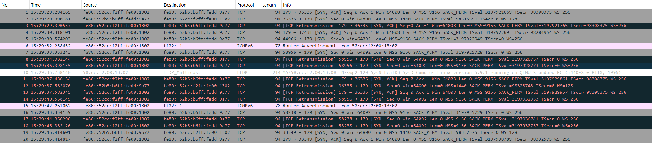
The capture shows the TCP SYN going out with no response from the far end — the connection never gets past the first step of the three-way handshake. Subsequently, after disabling several offload features on the interfaces, the BGP session recovered, so for now the problem can be narrowed to offload handling on this virtual forwarding path. That said, several features were disabled at once, and this set of symptoms alone is not enough to determine which specific one was responsible.
A short introduction to NIC offload#
NIC offload is the collective name for a family of techniques that hand packet processing work normally done by the CPU over to NIC hardware. At speeds above 10G, if every packet’s checksum calculation, segmentation and coalescing were handled by the CPU, that overhead alone could saturate a core. The common ones:
| Name | Full name | What it does |
|---|---|---|
| checksum offload | TX/RX Checksum Offload | The NIC calculates or verifies IP / TCP / UDP checksums |
| TSO | TCP Segmentation Offload | The stack hands down one large segment and the NIC splits it by MSS |
| GSO | Generic Segmentation Offload | The generic software version of TSO, splitting at the driver layer |
| GRO | Generic Receive Offload | On receive, merges multiple small packets into one large segment before handing it to the stack |
| LRO | Large Receive Offload | The earlier form of GRO, with more aggressive merging rules |
Both physical and virtual NICs may enable offload. The difference is that the processing chain in a virtual environment is longer: a packet may traverse the guest kernel, virtio, tap, the host’s virtual switch and an emulated device in turn. If any one of those layers handles offload metadata or checksum state inconsistently, you can get a situation where the packet can be captured but is ultimately discarded by the receiver.
In this lab the symptom was that LLDP, IPv6 neighbour discovery and ping all worked while TCP sessions could not establish. That combination helps narrow the search, but it cannot serve as a fixed diagnostic for all offload faults; whether a given protocol uses checksum offload is also affected by the kernel, the driver and the virtualisation implementation.
So the reliable conclusion here is not “virtual NICs always produce incorrect checksums”, but rather: on this link made up of PNetLab, Cumulus VX and a virtual switch, disabling several offload features at once only proves that this is an effective workaround — it does not yet fully confirm that the root cause lies in offload.
Typical symptoms#
This class of fault has a very recognisable signature: ping works, LLDP works, IPv6 RA works, and only TCP fails to come up. The reason is that different protocols take different paths:
- LLDP is a layer 2 protocol with no IP / TCP / UDP layer checksum, and the Ethernet FCS is calculated unconditionally by hardware, so it is unaffected.
- The checksums for ICMPv6 (including ping, RA and neighbour discovery) are calculated in software by the kernel on Linux and do not go through the offload path.
- TCP’s checksum and segmentation are precisely what the offload features cover.
So the link layer and the ICMP layer look entirely healthy and only TCP gets knocked out. If you ping once during troubleshooting and conclude the link is fine, you will head off in the wrong direction — checking routes, checking neighbours, checking configuration — while the real problem sits below the protocol stack.
How to disable it#
ethtool -k swp1 | grep -E 'tx-checksumming|rx-checksumming|tcp-segmentation|generic' shows the current state, and here everything is on:
cumulus@Leaf01:mgmt:~$ ethtool -k swp1 | grep -E 'tx-checksumming|rx-checksumming|tcp-segmentation|generic'
rx-checksumming: on [fixed]
tx-checksumming: on
        tx-checksum-ip-generic: on
tcp-segmentation-offload: on
        tx-tcp-segmentation: on
generic-segmentation-offload: on
generic-receive-offload: on
Turn them off one by one with ethtool:
sudo ethtool -K swp2 tx off rx off tso off gso off gro off
Disabling offload returns part of the processing to the software path, which is usually acceptable in a lab environment, but a production environment needs its CPU and throughput impact assessed. What is done here is only a troubleshooting and workaround measure in a virtual lab and should not be applied directly to production equipment.
Checking BGP state again, it has recovered:
Leaf03# show bgp summary

IPv4 Unicast Summary (VRF default):
BGP router identifier 10.255.255.5, local AS number 65004 vrf-id 0
BGP table version 75
RIB entries 13, using 2496 bytes of memory
Peers 2, using 40 KiB of memory

Neighbor        V         AS   MsgRcvd   MsgSent   TblVer  InQ OutQ  Up/Down State/PfxRcd   PfxSnt Desc
swp1            4      65001      2226      2301        0    0    0 00:08:41            5        7 N/A
swp2            4      65001        11        16        0    0    0 00:00:09            1        7 N/A

Total number of neighbors 2

L2VPN EVPN Summary (VRF default):
BGP router identifier 10.255.255.5, local AS number 65004 vrf-id 0
BGP table version 0
RIB entries 5, using 960 bytes of memory
Peers 2, using 40 KiB of memory

Neighbor        V         AS   MsgRcvd   MsgSent   TblVer  InQ OutQ  Up/Down State/PfxRcd   PfxSnt Desc
swp1            4      65001      2226      2301        0    0    0 00:08:41            4        5 N/A
swp2            4      65001        11        16        0    0    0 00:00:09            4        5 N/A

Total number of neighbors 2
Now to configure the main subject: ESI.
ESI multihoming configuration#
Warning: this section gives the first version of the configuration, which gets overturned twice later — once for LACP parameters not lining up (changing the Port-Channel number and the system priority), and once for ESI type incompatibility (Type 3 changed to Type 0). If you just want a working configuration, skip to “The complete configuration as of the end of this article” at the bottom.
Again, I will not explain the commands — see the official documentation if you are interested.
Leaf01 and Leaf03#
This is Leaf01’s configuration. Leaf03’s is the same apart from source address, so it is not shown.
nv set evpn multihoming enable on
nv set interface swp1,swp2 evpn multihoming uplink on

nv set interface bond1 bond member swp3
nv set interface bond1 bond lacp-rate fast
nv set interface bond1 evpn multihoming segment local-id 1
nv set interface bond1 evpn multihoming segment mac-address 44:38:39:be:ef:aa
nv set interface bond1 bridge domain br_default access 10

nv config apply
nv config save
Leaf02 and Leaf04#
Leaf04’s configuration is not pasted either — it is the same, just change the rd.
interface Port-Channel10
   switchport access vlan 10
   evpn ethernet-segment
      identifier 0344:3839:beef:aa00:0001
      route-target import 44:38:39:be:ef:aa
   lacp system-id 4438.39be.efaa

interface Ethernet5
   channel-group 10 mode active
   lacp timer fast
Note that Arista’s identifier 0344:3839:beef:aa00:0001 and the 03:44:38:39:be:ef:aa:00:00:01 that Cumulus derives from local-id 1 plus mac-address 44:38:39:be:ef:aa are two ways of writing the same value — the two sides are aligned. At least, that is how it looks in the configuration text.
Host#
An Ubuntu Docker image is used here.
ip link add bond0 type bond mode 802.3ad lacp_rate fast
ip link set eth1 down
ip link set eth2 down
ip link set eth3 down
ip link set eth4 down
ip link set eth1 master bond0
ip link set eth2 master bond0
ip link set eth3 master bond0
ip link set eth4 master bond0
ip link set eth1 up
ip link set eth2 up
ip link set eth3 up
ip link set eth4 up
ip addr add 192.168.100.10/24 dev bond0
ip link set bond0 up
Verifying the configuration#
Before verifying, it is worth filling in some background on bonds — without it there is no way to approach the troubleshooting.
Understanding the Linux bond#
/proc/net/bonding/bond0 is the most direct view there is when troubleshooting a multihomed attachment. Its output carries a lot of information, but only a few places really need watching.
Confirm the mode#
Bonding Mode: IEEE 802.3ad Dynamic link aggregationLinux bonding has seven modes. In this article’s Linux bond + all-active ESI multihoming lab, the bond must use 802.3ad (LACP). With single-active, the access side does not necessarily need LACP. Only 802.3ad emits LACP PDUs, and only it allows multiple upstream PEs to be recognised as one logical partner. The other modes rely either on MAC learning or on active/standby switchover, neither of which lines up with an Ethernet Segment. So if this line is not 802.3ad, there is no point reading further.
The aggregator#
Active Aggregator Info:
        Aggregator ID: 1
        Number of ports: 2
        Actor Key: 15
        Partner Key: 9
        Partner Mac Address: 44:38:39:be:ef:aa
Number of ports is the line to read first in the whole output — it directly answers how many links are actually in use. Four uplinks in a multihomed attachment showing 1 means aggregation has failed and the other three are idle.
Each slave is also labelled with its own Aggregator ID. Linux groups slaves into the same aggregator on two criteria: the partner’s system ID (system priority + system MAC) and the partner’s oper key. If either of those differs, the slave is assigned to a different aggregator, and Linux only activates one of them at a time. This is also the most common trap in cross-vendor multihoming: a consistent ESI only guarantees that the switch side considers itself one segment; whether the CE agrees depends on those two values.
The port state bitmap#
Each slave has a port state for both actor and partner, an 8-bit map:
| bit | value | meaning |
|---|---|---|
| 0 | 1 | LACP Activity — actively sends LACP |
| 1 | 2 | Short Timeout — fast timeout (1 second) |
| 2 | 4 | Aggregation — the port can aggregate |
| 3 | 8 | Synchronization — synchronised |
| 4 | 16 | Collecting — receiving has started |
| 5 | 32 | Distributing — sending has started |
| 6 | 64 | Defaulted — no partner PDU received, using defaults |
| 7 | 128 | Expired — the partner’s information has timed out |
Some common combinations:
| value | breakdown | state |
|---|---|---|
| 63 | 1+2+4+8+16+32 | Fully working, fast timeout, both sending and receiving |
| 61 | 1+4+8+16+32 | Fully working, slow timeout |
| 15 | 1+2+4+8 | Synchronised, but no Collecting/Distributing — sitting there not forwarding |
| 7 | 1+2+4 | Not even synchronised |
| 69 | 1+4+64 | Carries Defaulted, meaning no partner PDU was received at all |
The most valuable distinction when troubleshooting is between 15 and 63. Both indicate the link is up and LACP is being exchanged; 15 means this link has been judged ineligible to join the current aggregation group and is on standby, generally because system ID or oper key does not match.
Churn state#
Actor Churn State: none
Partner Churn State: none
Actor Churned Count: 0
Partner Churned Count: 1
The churn detection mechanism exists to spot a port that has been unable to complete synchronisation for a long time. Three values:
none— converged normally, no churn has occurredmonitoring— detection in progresschurned— timed out and still not synchronised
Churned Count is a cumulative count. A count that keeps growing means the link is repeatedly attempting to aggregate and repeatedly failing, which often says more than the instantaneous state does — sometimes the moment you happen to look is one where it is synchronised, while the counter reveals it has been flapping all along.
Physical layer state#
Slave Interface: eth1
MII Status: up
Speed: 10000 Mbps
Duplex: full
Link Failure Count: 1
MII Status is the lowest-level judgement, with values up / down / going down. If it is down, the problem is in the physical layer or the virtual link and has nothing to do with LACP. Link Failure Count records how many times the link has flipped; non-zero means this line has gone down at some point.
Quick reference order#
Reading in this order when troubleshooting aggregation problems gets you to the right layer quickly:
Bonding Mode          →  if it is not 802.3ad, stop here
MII Status            →  if down, it is a physical/virtual link problem
Number of ports       →  fewer than expected means some slave is not in the aggregation group
Aggregator ID         →  are all the slaves in the same aggregator?
partner system/key    →  when they are not, check which of these two does not match
port state            →  15 is standby, 63/61 are forwarding normally
Churned Count         →  continuous growth means repeated flapping
Checking the bond state#
On the host, cat /proc/net/bonding/bond0 shows how the interface is running. Going through it in the order above:
Bonding Mode: IEEE 802.3ad Dynamic link aggregation— mode is right, carry on.- All four slaves show
MII Status: up— no physical layer problem. Number of ports: 2, but bond0 has four interfaces bonded into it, so two have not joined the active aggregator.- Looking at each slave’s
Aggregator ID: eth1 and eth3 are in aggregator 2, eth2 and eth4 in aggregator 3 — the four links have been split into two groups. - Comparing the partner parameters of the two groups, the difference is obvious:
| eth1 / eth3 (Leaf01, Leaf03) | eth2 / eth4 (Leaf02, Leaf04) | |
|---|---|---|
| partner system MAC | 44:38:39:be:ef:aa | 44:38:39:be:ef:aa |
| partner system priority | 65535 | 32768 |
| partner oper key | 9 | 10 |
| port state | 63 | 15 |
The system MACs match on both sides, which shows lacp system-id was paired up correctly; but system priority and oper key both differ. By the criteria described above, the host concludes these are two different aggregation groups on two different devices, so it builds two aggregators and, under the ad_select stable policy, activates only one of them. The port states confirm this: 63 is synchronised with both sending and receiving enabled, 15 is synchronised but without Collecting/Distributing, sitting on standby. Time to change the configuration.
root@Docker:/home# cat /proc/net/bonding/bond0
Ethernet Channel Bonding Driver: v3.7.1 (April 27, 2011)

Bonding Mode: IEEE 802.3ad Dynamic link aggregation
Transmit Hash Policy: layer2 (0)
MII Status: up
MII Polling Interval (ms): 100
Up Delay (ms): 0
Down Delay (ms): 0

802.3ad info
LACP rate: fast
Min links: 0
Aggregator selection policy (ad_select): stable
System priority: 65535
System MAC address: 50:00:00:11:00:01
Active Aggregator Info:
        Aggregator ID: 2
        Number of ports: 2
        Actor Key: 15
        Partner Key: 9
        Partner Mac Address: 44:38:39:be:ef:aa

Slave Interface: eth1
MII Status: up
Speed: 10000 Mbps
Duplex: full
Link Failure Count: 0
Permanent HW addr: 50:00:00:11:00:01
Slave queue ID: 0
Aggregator ID: 2
Actor Churn State: none
Partner Churn State: none
Actor Churned Count: 0
Partner Churned Count: 0
details actor lacp pdu:
    system priority: 65535
    system mac address: 50:00:00:11:00:01
    port key: 15
    port priority: 255
    port number: 1
    port state: 63
details partner lacp pdu:
    system priority: 65535
    system mac address: 44:38:39:be:ef:aa
    oper key: 9
    port priority: 255
    port number: 1
    port state: 63

Slave Interface: eth2
MII Status: up
Speed: 10000 Mbps
Duplex: full
Link Failure Count: 0
Permanent HW addr: 50:00:00:11:00:02
Slave queue ID: 0
Aggregator ID: 3
Actor Churn State: churned
Partner Churn State: none
Actor Churned Count: 5
Partner Churned Count: 0
details actor lacp pdu:
    system priority: 65535
    system mac address: 50:00:00:11:00:01
    port key: 15
    port priority: 255
    port number: 2
    port state: 7
details partner lacp pdu:
    system priority: 32768
    system mac address: 44:38:39:be:ef:aa
    oper key: 10
    port priority: 32768
    port number: 5
    port state: 15

Slave Interface: eth3
MII Status: up
Speed: 10000 Mbps
Duplex: full
Link Failure Count: 0
Permanent HW addr: 50:00:00:11:00:03
Slave queue ID: 0
Aggregator ID: 2
Actor Churn State: none
Partner Churn State: none
Actor Churned Count: 1
Partner Churned Count: 1
details actor lacp pdu:
    system priority: 65535
    system mac address: 50:00:00:11:00:01
    port key: 15
    port priority: 255
    port number: 3
    port state: 63
details partner lacp pdu:
    system priority: 65535
    system mac address: 44:38:39:be:ef:aa
    oper key: 9
    port priority: 255
    port number: 1
    port state: 63

Slave Interface: eth4
MII Status: up
Speed: 10000 Mbps
Duplex: full
Link Failure Count: 0
Permanent HW addr: 50:00:00:11:00:04
Slave queue ID: 0
Aggregator ID: 3
Actor Churn State: churned
Partner Churn State: none
Actor Churned Count: 4
Partner Churned Count: 1
details actor lacp pdu:
    system priority: 65535
    system mac address: 50:00:00:11:00:01
    port key: 15
    port priority: 255
    port number: 4
    port state: 7
details partner lacp pdu:
    system priority: 32768
    system mac address: 44:38:39:be:ef:aa
    oper key: 10
    port priority: 32768
    port number: 5
    port state: 15
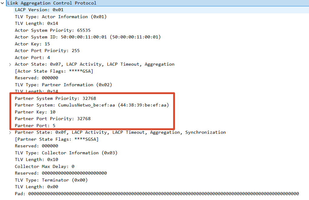
The same information is confirmed in a capture — Partner Key: 10 and Partner System Priority: 32768:
Fixing the bond#
First fix the system priority mismatch. Cumulus defaults its LACP system priority to 65535 and Arista defaults to 32768, so the two do not match. On Leaf02 and Leaf04:
lacp system-priority 65535
Next, fix the oper key. What is an oper key, anyway? It is a 16-bit value from 802.1AX whose job is to identify which ports on the same device can be bundled together. Putting it alongside the system ID makes it much easier to understand:
| Parameter | What it answers |
|---|---|
| system ID | Which device do these links lead to |
| oper key | Which aggregation group on that device |
As for where the oper key value comes from, 802.1AX does not specify it — each vendor decides for itself, and I could find no documentation on it. From the information below: Cumulus’s bond1 has oper key 9, which offers no clue at all; Arista’s key and the Port-Channel number look identical, which suggests they might be related. So let me try changing Arista’s Port-Channel10 to Port-Channel9 and see.
| Device | oper key |
|---|---|
Cumulus bond1 | 9 |
Arista Port-Channel10 | 10 |
First run the following on Leaf02 — the ESI configuration has to move across with it:
default interface Ethernet5
!
no interface Port-Channel10
!
interface Port-Channel9
   switchport access vlan 10
   evpn ethernet-segment
      identifier 0344:3839:beef:aa00:0001
      route-target import 44:38:39:be:ef:aa
   lacp system-id 4438.39be.efaa
!
interface Ethernet5
   channel-group 9 mode active
   lacp timer fast
From the host’s output below, the interface came up, so the idea that the Port-Channel ID corresponds to the oper key looks right. Let me change it a couple of times on Leaf04 to confirm.
802.3ad info
LACP rate: fast
Min links: 0
Aggregator selection policy (ad_select): stable
System priority: 65535
System MAC address: 50:00:00:11:00:01
Active Aggregator Info:
        Aggregator ID: 2
        Number of ports: 3
        Actor Key: 15
        Partner Key: 9
        Partner Mac Address: 44:38:39:be:ef:aa
***
Slave Interface: eth2
***
details partner lacp pdu:
    system priority: 65535
    system mac address: 44:38:39:be:ef:aa
    oper key: 9
    port priority: 32768
    port number: 5
    port state: 63
The commands below change the Port-Channel ID on Leaf04 to 110, to test the hypothesis once more.
default interface Ethernet5
!
no interface Port-Channel10
!
interface Port-Channel110
   switchport access vlan 10
   evpn ethernet-segment
      identifier 0344:3839:beef:aa00:0001
      route-target import 44:38:39:be:ef:aa
   lacp system-id 4438.39be.efaa
!
interface Ethernet5
   channel-group 110 mode active
   lacp timer fast
From the capture and the host interface information below, the oper key became 110, confirming the earlier hypothesis. Once verified, the Port-Channel ID needs changing back to 9 — not shown here. Next, verify the ESI state on the leaf nodes.
details partner lacp pdu:
    system priority: 32768
    system mac address: 44:38:39:be:ef:aa
    oper key: 110
    port priority: 32768
    port number: 5
    port state: 15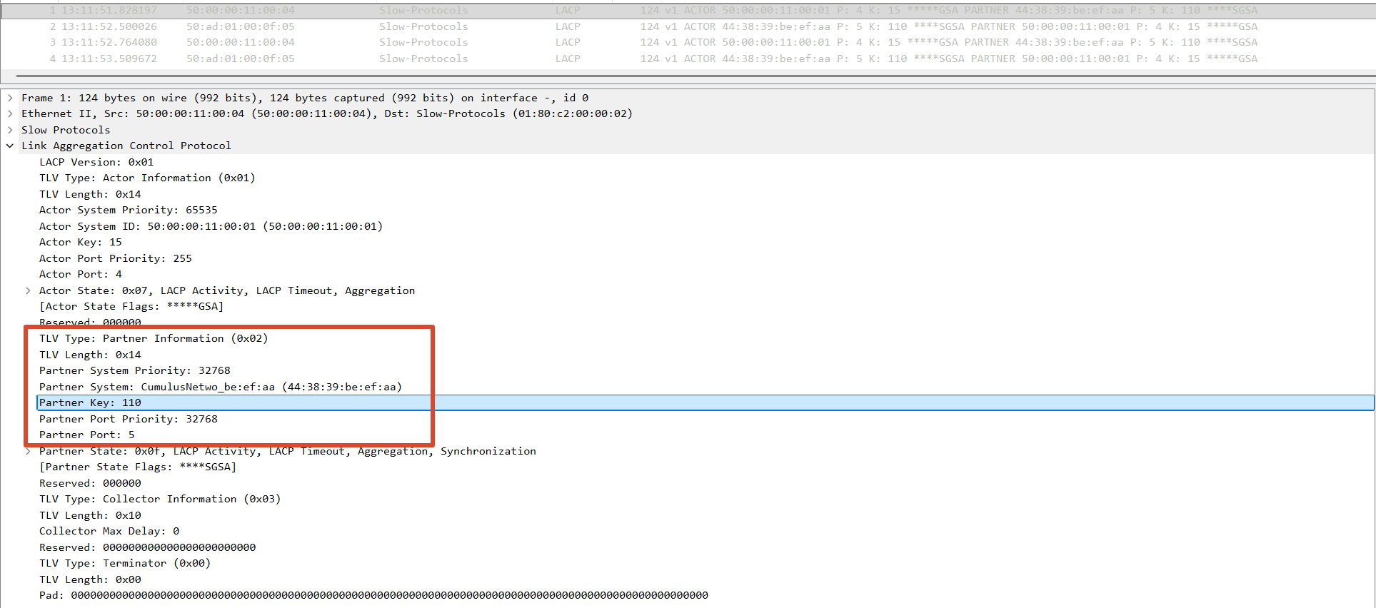
Once the changes are complete, the host’s bond state should look like this:
802.3ad info
LACP rate: fast
Min links: 0
Aggregator selection policy (ad_select): stable
System priority: 65535
System MAC address: 50:00:00:11:00:01
Active Aggregator Info:
        Aggregator ID: 2
        Number of ports: 4
        Actor Key: 15
        Partner Key: 9
        Partner Mac Address: 44:38:39:be:ef:aa
Verifying the ESI#
With bond aggregation working, go back to the switch side and see whether EVPN has really recognised these devices as one segment. Running this on Leaf01 gives the result below: the VTEPs list contains only 10.255.255.5, the other Cumulus (Leaf03). A four-device segment has recognised only two, and neither Arista is in it. The bond has all four links aggregated, and here there are only two — which shows that the access side accepting it does not mean the switch side has. The host judges on LACP system ID and oper key; EVPN judges on ESI. Two planes, each reaching its own verdict.
cumulus@Leaf01:mgmt:~$ sudo vtysh -c "show evpn es"
Type: B bypass, L local, R remote, N non-DF
ESI                            Type ES-IF                 VTEPs
03:44:38:39:be:ef:aa:00:00:01  LR   bond1                 10.255.255.5
Looking at what is actually in effect on Leaf02:
Leaf02#show run int port-Channel 9
interface Port-Channel9
   switchport access vlan 10
   !
   evpn ethernet-segment
      route-target import 44:38:39:be:ef:aa
   lacp system-id 4438.39be.efaa
When the configuration was pushed earlier, the identifier line never went in. It was silently dropped during the paste, leaving only route-target import. With no ESI value, Arista naturally does not generate a Type-4 route. Typing it in by hand shows why:
Leaf02(config)#interface port-Channel 9
Leaf02(config-if-Po9)#evpn ethernet-segment
Leaf02(config-evpn-es)#identifier 0344:3839:beef:aa00:0001
% Unable to configure identifier because only Type 0 ESID is supported
The error says it plainly: this version of EOS supports Type 0 only. And the 03:44:38:39:be:ef:aa:00:00:01 that Cumulus derived from mac-address plus local-id has a leading byte of 03 — Type 3. Checking the options on the Cumulus side:
cumulus@Leaf01:mgmt:~$ nv set interface bond1 evpn multihoming segment ?
    identifier             Ethernet segment identifier Type-0 format, it must be unique for each segment and match other bonds in the segment.
    local-id               Ethernet segment local-id.  If provided, it will be combined with the global multihoming `mac-address` to create the ethernet segment identifier...
    mac-address            MAC address for this ethernet segment...
Cumulus can do both: local-id takes the Type 3 derivation path, identifier specifies Type 0 directly. So Type 0 is what both sides support, which means changing the Cumulus side.
| ESI types supported | |
|---|---|
| Cumulus 5.9.1 | Type 3 (derived from local-id) or Type 0 (specified directly with identifier) |
| Arista EOS 4.32.4M | Type 0 only |
The two parameters are mutually exclusive — adding identifier directly is rejected:
cumulus@Leaf01:mgmt:~$ nv set interface bond1 evpn multihoming segment identifier 00:11:22:33:44:55:66:77:88:99
Invalid config [rev_id: 10]
  Config invalid at interface.bond1.evpn.multihoming.segment.enable: If `segment` is enabled, either `local-id` or `identifier` must be set but not both.
Remove local-id and specify the full Type 0 value directly. mac-address no longer participates in deriving the ESI, but it is kept here so that the LACP system MAC stays consistent between the two vendors. On both Cumulus boxes:
nv unset interface bond1 evpn multihoming segment local-id
nv set interface bond1 evpn multihoming segment identifier 00:11:22:33:44:55:66:77:88:99
nv config apply
Both Arista boxes change to the same value, and the ES-Import RT has to change with it — the original 44:38:39:be:ef:aa was the system MAC portion of the Type 3 ESI. Both Aristas move to the same Type 0 ESI. The ES-Import RT needs to stay consistent across all members, and in this lab it is set manually to 11:22:33:44:55:66:
interface Port-Channel9
   evpn ethernet-segment
      identifier 0011:2233:4455:6677:8899
      route-target import 11:22:33:44:55:66
After that, verifying again on Leaf01, all three peers are present — two Cumulus and two Arista. At this point the four devices have completed member discovery using the same ESI, the Type-4 routes and the host-side LACP aggregation have both recovered, and cross-vendor control plane interoperability can be confirmed. The actual forwarding behaviour of DF, BUM, split horizon and aliasing still needs verifying through data plane experiments.
cumulus@Leaf01:mgmt:~$ sudo vtysh -c "show evpn es"
Type: B bypass, L local, R remote, N non-DF
ESI                            Type ES-IF                 VTEPs
00:11:22:33:44:55:66:77:88:99  LRN  bond1                 10.255.255.4,10.255.255.5,10.255.255.6
Note that Type has gone from LR to LRN — an N has appeared, so Leaf01 is now non-DF. With the membership going from two devices to four, the DF was re-elected and changed hands.
The basic overlay came up along with it:
cumulus@Leaf01:mgmt:~$ sudo vtysh -c "show evpn vni 10010"
VNI: 10010
 Type: L2
 Local VTEP IP: 10.255.255.3
 Remote VTEPs for this VNI:
  10.255.255.5 flood: HER
  10.255.255.6 flood: HER
  10.255.255.4 flood: HER
 Number of MACs (local and remote) known for this VNI: 2
Looking at the Type-4 routes from Leaf04, all four entries are there with identical ESI values:
Leaf04#show bgp evpn route-type ethernet-segment
          Network                Next Hop              Metric  LocPref Weight  Path
 * >Ec    RD: 10.255.255.3:3 ethernet-segment 0011:2233:4455:6677:8899 10.255.255.3
 * >Ec    RD: 10.255.255.4:1 ethernet-segment 0011:2233:4455:6677:8899 10.255.255.4
 * >Ec    RD: 10.255.255.5:3 ethernet-segment 0011:2233:4455:6677:8899 10.255.255.5
 * >      RD: 10.255.255.6:1 ethernet-segment 0011:2233:4455:6677:8899 10.255.255.6
Each device uses its own loopback as RD and next hop; the last entry is Leaf04’s own (next hop -). The Ec in the status codes means the same route was received once via each of the two spines, forming ECMP — the maximum-paths configured in the underlay earlier showing up here.
The fourth difference: the DF election algorithm#
The two vendors use different DF election algorithms, which surfaced while looking at show evpn es detail:
cumulus@Leaf01:mgmt:~$ sudo vtysh -c "show evpn es detail"
ESI: 00:11:22:33:44:55:66:77:88:99
 Type: Local,Remote
 Interface: bond1
 State: up
 DF status: non-df
 DF preference: 32767
 VTEPs:
     10.255.255.4     10.255.255.4(local) df_alg: service-carving df_pref: 0
     10.255.255.5     10.255.255.5(local) df_alg: preference df_pref: 32767
     10.255.255.6     10.255.255.6(local) df_alg: service-carving df_pref: 0
In the df_alg column, the two Cumulus boxes show preference and the two Arista boxes show service-carving. The default DF election defined by RFC 7432 uses the modulus algorithm; RFC 8584 defines an extensible DF election framework and the DF Election Extended Community; and the current algorithm number 2, Preference-Based DF Election, is defined by RFC 9785. The algorithm number and preference value that Cumulus advertises can be seen directly in the Type-4 route:
*> [4]:[00:11:22:33:44:55:66:77:88:99]:[32]:[10.255.255.3]
                    ET:8 ES-Import-Rt:11:22:33:44:55:66 DF: (alg: 2, pref: 32767)
Arista’s corresponding entry has no DF: extended community, which therefore indicates the default algorithm. Under RFC 8584’s compatibility handling, as long as the PEs in the same ES have not consistently advertised the same algorithm, all of them should fall back to the RFC 7432 default. Next, check each vendor’s local DF state:
cumulus@Leaf01:mgmt:~$ sudo vtysh -c "show evpn es detail"
ESI: 00:11:22:33:44:55:66:77:88:99
 Interface: bond1
 State: up
 DF status: non-df
 DF preference: 32767
cumulus@Leaf03:mgmt:~$ sudo vtysh -c "show evpn es detail"
ESI: 00:11:22:33:44:55:66:77:88:99
 Interface: bond1
 State: up
 DF status: non-df
 DF preference: 32767
Both say non-df. You cannot directly compare 32767 against 0 here, because the segment members are not running the same DF algorithm. Per RFC 8584, when the advertised algorithms are inconsistent the fallback should be to the default algorithm; what actually needs checking is whether each device’s post-fallback calculation agrees. So, Arista’s result:
Leaf04#show bgp evpn instance
EVPN instance: VLAN 10
  Local ethernet segment:
    ESI: 0011:2233:4455:6677:8899
      Interface: Port-Channel9
      Mode: all-active
      State: up
      ES-Import RT: 11:22:33:44:55:66
      DF election algorithm: modulus
      Designated forwarder: 10.255.255.5
      Non-Designated forwarder: 10.255.255.3
      Non-Designated forwarder: 10.255.255.4
      Non-Designated forwarder: 10.255.255.6
Leaf02’s output is identical. The modulus result computed by both Arista boxes is 10.255.255.5, i.e. Leaf03. Working RFC 7432’s service carving by hand confirms it: sort the four by ascending IP as .3/.4/.5/.6, numbered 0 to 3, take VLAN 10 modulo 4 — 10 mod 4 = 2 — landing on ordinal 2, which is exactly 10.255.255.5. Arista’s arithmetic is correct. The problem is that Leaf03 says it is non-df.
Assembling all four devices’ self-assessments:
| Device | Cumulus believes | Arista believes |
|---|---|---|
| Leaf01 (.3) | non-df | non-DF |
| Leaf02 (.4) | — | non-DF |
| Leaf03 (.5) | non-df | DF |
| Leaf04 (.6) | — | non-DF |
Arista designates Leaf03 as DF and Leaf03 does not accept the appointment. Trying a different level — DF election is really per ES plus EVI (per VNI), so perhaps the ES-level summary does not represent the actual assignment for VNI 10010:
cumulus@Leaf01:mgmt:~$ sudo vtysh -c "show evpn es-evi detail"
VNI 10010 ESI: 00:11:22:33:44:55:66:77:88:99
 Type: L
 Ready for BGP: yes
No DF information here either. By this point it is clear enough: each vendor’s show only reflects its own view, those views are themselves inconsistent, and digging through more commands just produces more of each talking past the other.
The complete configuration as of the end of this article#
This is the state after all the changes above have been applied: the Type 0 ESI is unified, the three LACP parameters are aligned, all four uplinks are aggregated, and the four leaves can see each other. The DF algorithm is not yet aligned — that is for part 2.
Leaf01 (Cumulus 5.9.1)#
For Leaf03, change hostname, interface lo ip address, nve vxlan source address, router bgp router-id and interface vlan10 ip address to the corresponding values; everything else is identical.
nv set system hostname Leaf01

nv set interface lo type loopback
nv set interface lo ip address 10.255.255.3/32
nv set interface eth0 type eth
nv set interface eth0 ip address dhcp
nv set interface eth0 ip vrf mgmt
nv set interface swp1-3 type swp
nv set interface swp1-3 link mtu 1500

nv set router bgp enable on
nv set router bgp autonomous-system 65002
nv set router bgp router-id 10.255.255.3
nv set vrf default router bgp enable on
nv set vrf default router bgp neighbor swp1 type unnumbered
nv set vrf default router bgp neighbor swp1 remote-as external
nv set vrf default router bgp neighbor swp2 type unnumbered
nv set vrf default router bgp neighbor swp2 remote-as external
nv set vrf default router bgp address-family ipv4-unicast enable on
nv set vrf default router bgp address-family ipv4-unicast redistribute connected enable on
nv set vrf default router bgp address-family l2vpn-evpn enable on
nv set vrf default router bgp neighbor swp1 address-family l2vpn-evpn enable on
nv set vrf default router bgp neighbor swp2 address-family l2vpn-evpn enable on
nv set vrf default router bgp path-selection multipath aspath-ignore on

nv set evpn enable on
nv set evpn vni 10010 route-target both 10:10
nv set nve vxlan enable on
nv set nve vxlan source address 10.255.255.3
nv set nve vxlan arp-nd-suppress on

nv set bridge domain br_default vlan 10
nv set bridge domain br_default vlan 10 vni 10010

nv set interface vlan10 type svi
nv set interface vlan10 vlan 10
nv set interface vlan10 base-interface br_default
nv set interface vlan10 ip address 192.168.100.2/24
nv set interface vlan10 ip vrr enable on
nv set interface vlan10 ip vrr address 192.168.100.1/24
nv set interface vlan10 ip vrr mac-address 00:00:5e:00:01:01

nv set evpn multihoming enable on
nv set interface swp1-2 evpn multihoming uplink on
nv set interface bond1 type bond
nv set interface bond1 bond member swp3
nv set interface bond1 bond lacp-rate fast
nv set interface bond1 bridge domain br_default access 10
nv set interface bond1 evpn multihoming segment enable on
nv set interface bond1 evpn multihoming segment identifier 00:11:22:33:44:55:66:77:88:99
nv set interface bond1 evpn multihoming segment mac-address 44:38:39:be:ef:aa

nv config apply
nv config save
The line segment mac-address 44:38:39:be:ef:aa no longer participates in deriving the ESI, but it determines the LACP system MAC that Cumulus emits, and that has to match Arista’s lacp system-id.
Leaf02 (Arista vEOS-lab 4.32.4M)#
For Leaf04, change Loopback0, router-id, network and rd to the corresponding values.
lacp system-priority 65535
!
vlan 10
!
interface Port-Channel9
   switchport access vlan 10
   !
   evpn ethernet-segment
      identifier 0011:2233:4455:6677:8899
      route-target import 11:22:33:44:55:66
   lacp system-id 4438.39be.efaa
!
interface Ethernet1
   no switchport
   ipv6 enable
   ipv6 nd ra interval msec 4000 3000
   ipv6 nd ra lifetime 10
!
interface Ethernet2
   no switchport
   ipv6 enable
   ipv6 nd ra interval msec 4000 3000
   ipv6 nd ra lifetime 10
!
interface Ethernet5
   channel-group 9 mode active
   lacp timer fast
!
interface Loopback0
   ip address 10.255.255.4/32
!
interface Vlan10
   ip address virtual 192.168.100.1/24
!
interface Vxlan1
   vxlan source-interface Loopback0
   vxlan udp-port 4789
   vxlan vlan 10 vni 10010
!
ip routing ipv6 interfaces
!
ipv6 unicast-routing
!
router bgp 65003
   router-id 10.255.255.4
   maximum-paths 2 ecmp 2
   neighbor SPINE peer group
   neighbor SPINE send-community extended
   neighbor interface Et1-2 peer-group SPINE remote-as 65001
   !
   vlan 10
      rd 10.255.255.4:10
      route-target both 10:10
      redistribute learned
   !
   address-family evpn
      neighbor SPINE activate
   !
   address-family ipv4
      neighbor SPINE activate
      neighbor SPINE next-hop address-family ipv6 originate
      network 10.255.255.4/32
   !
   address-family ipv6
      neighbor SPINE activate
Three things in this configuration exist purely to align with Cumulus, and none of them are visible as such from the configuration text alone:
lacp system-priority 65535— aligns with the Cumulus default; EOS’s own default is 32768- the
Port-Channel9number itself — aligns with the oper key 9 derived from Cumulus’s bond1 lacp system-id 4438.39be.efaa— aligns with Cumulus’s default es-sys-mac
Change the value of any one of those three and the aggregation on the host side will not come up — with no error message of any kind.
Summary#
At this point, cross-vendor integration has run into five differences in total: four solved, one left for part 2.
| Difference | Cumulus 5.9.1 | Arista 4.32.4M | Symptom | Status in this article |
|---|---|---|---|---|
| ESI type | Can derive Type 3, can also specify Type 0 | Type 0 only | Direct error when typed, silently discarded when pasted | Unified on Type 0 |
| LACP system priority | Default 65535 | Default 32768 | Number of ports will not come up | Aligned |
| LACP oper key | Derived from the bond | Follows the Port-Channel number | As above | Aligned |
| LACP system MAC | es-sys-mac default | Requires manual lacp system-id | No warning; get it wrong and it simply does not aggregate | Aligned |
| DF election algorithm | preference (algorithm 2, standardised in RFC 9785) | modulus (RFC 7432 default) | The two vendors report different DF results | Unsolved |
The first four are all explicit: either the command errors out directly, or Number of ports is sitting there plainly wrong, and following the trail always gets you to a fix. The fifth is different. BGP neighbours, ES membership, Type-4 routes and host-side LACP are all healthy, and yet the devices do not agree on who the DF is.
In that situation show is no longer any help, because show output alone can no longer adjudicate actual forwarding behaviour: the two vendors’ control plane outputs contradict each other, and those outputs alone are not enough to determine which side is actually forwarding BUM by which path. Part 2 stops trusting show and uses multi-point captures and real BUM traffic to settle it, while also verifying the remaining three mechanisms — fast withdrawal, split horizon and aliasing.
References
- RFC 7432 — BGP MPLS-Based Ethernet VPN
- RFC 8365 — A Network Virtualization Overlay Solution Using EVPN
- RFC 9785 — Preference-Based EVPN Designated Forwarder Election
- RFC 8584 — Framework for EVPN Designated Forwarder Election Extensibility
- IEEE 802.1AX — Link Aggregation
- NVIDIA Cumulus Linux 5.9 — EVPN Multihoming
- Arista EOS — EVPN
- Linux kernel — bonding and checksum offloads